The FC frame header has not changed since its inception back in the late 80-ies. This shows the absolute rock-solid backward compatibility towards previous generation platforms and vendors. Obviously the the FC protocol itself has grown and evolved with marked demands to provide an extremely flexible transport mechanism for the most demanding storage environments. When you start to design a new protocol the concept of future proofing is a must and sits very high on the top of the design list. Not only does it require insight into current markets and requirements but also a huge set of extremely smart brains to come up with possible scenario’s of what might be required in years to come. You don’t want it to become obsolete in 5 years time because there were inherent flaws in the protocol. Next to that your have to facilitate options which allows for flexible expansion of functions and features of which none of the above brains had ever thought of. (Did somebody know about VMware back in 1990?) The concepts of NPIV where not on the radar back then. So what is the structure of this protocol that makes it so flexible.
As with all transmission protocols there are certain characteristics that sit at the foundation of each of them. For Fibre Channel this always has been to sit on the edge of the technical speeds&feeds capabilities in combination with the ability to reliably move upper layer channel protocols (such as IPI, HIPPI, SCSI) added with the flexibility to easily map and expand other protocols on top of it which were inherently limited to technical abilities. FC ran 200MB/s when Ethernet was just ramping up to 100Mb/s. I mentioned reliability, FC requires a 10^-12 BER bit error rate or less. this basically means that by design it allows only 1 bit to flip (for whatever reason) in 1000000000000 bits.
The header
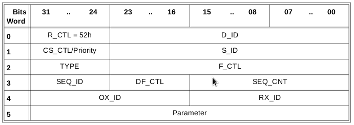
The generic FC header consists of 24 bytes preceded by a 4 byte Start-of-Frame (SOF) followed by a 2112 byte data field and 8 bytes CRC+ End-of-Frame. Nothing new here. Dissecting the header you’ll see that the first byte contains a R_CTL field. This field more or less determines the characteristics of the frame. Is it a normal data frame, an link service frame, an inter-switch control frame etc. the second byte contains the 24bits FCID destination address. The reason why it sits there is because this allows the fabric routing logic to immediately make the correct routing decisions in the shortest possible time.
For this article I’ll focus on only one more field namely the DF_CTL field later on.

As you can see there are some limitation when you take into account certain features which we now take for granted. One example is FC routing (the ability to to send frames between two or more logically separated fabrics. In the standard frame header (and especially the source and destination address fields) is no room for inter fabric addressing. Furthermore there may be upper layer protocols that could require more information from a transport perspective in order to route the data to its final destination which may not even be a FC device. (IP over FC is such an example). In the above two examples (FC routing and ULP extended info) the FC frameheader will be adjusted with so called “Extended Headers” and/or “Optional Headers” respectively.
Extended Header
The extended header will, as the name implies, extend the FC header by prepending additional routing fields in front of the normal start of the frame. This extension currently allows for 3 routing topologies to be applied to the frame.
- VFT – Virtual Fabric Tagging header
- IFR – Inter-Fabric Routing header
- ENC – Encapsulation header
VFT
The R_CTL field on the extended header will start with either 0x50, 0x51 or 0x52 respectively. The VFT allows for a frame to be tagged with a certain Virtual Fabric ID or the virtual fabric it belongs to.

For the sake of simplicity I’ll use a Brocade example here but Cisco offers the same or similar functionality.
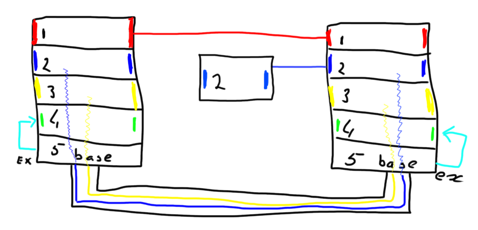
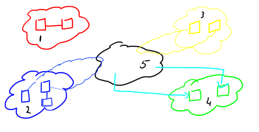
In the above example (again, pardon my drawing) I’ve depicted the current capabilities of how interswitch and interfabric connectivity may be achieved. Each of the 2 physical switch is divided into 5 logical fabrics each having a unique domain in that fabric. The RED fabric consists of two logical switches directly connected via a normal ISL or E-port. The BLUE and YELLOW fabric make us of, so called, XISL (or extended ISL). These are virtual ISL’s going from the virtual switch towards the BASE switch after which the frame is transported to its destination on the remote chassis. The GREEN fabric is connected via EX-ports to the base switch. This allows for frames to be routed from any of the other fabrics, either inside the same chassis or a remote chassis, except the RED fabric since that on is isolated in this particular scenario. Logically these fabrics look like this:
So if a frame needs to be sent from domain 1 in the BLUE fabric to domain 2 in the BLUE fabric it will be expanded with an extended header whereby the R_CTL field will be filled with a 0x50 value and the VF_ID be given a value between 0x001 and 0xEFF (The remainder of the VF tags are reserved for other purposes) assuming the virtual fabric has already formed. The CRC will be recomputed and is now based upon not only the original frame but now also includes the extended header. The VF_ID value is determined during a fabric build and is configurable via the respective management interfaces. The frame including the VFT header will be sent to the “BASE” switch and this one looks at the VFT header in order to determine which exit port it needs to be sent. Upon arrival at the remote BASE switch this one will determine to which VF it needs to be sent inside this chassis based upon the VF_ID tag. As soon as the frame enters that particular logical switch the extended header will be stripped off, the CRC will be recomputed based on the original frame and it is now logically sent to its destination. Remember that this destination may also be another switch hanging off an E-port of the switch in question. As shown above the single switch connected to the BLUE fabric from the right chassis is such an example. This one is connected via one or more normal E-ports.
IFR
The IFR header will be applied in the above method when frames need to traverse from virtual fabrics 1,2 or 3 into fabric 4 or vice-versa. (remember a BASE switch cannot contain F-ports so there is no such thing as a routed “back-bone” concept as you could have with he 7500 and 7800 routers). It has no notion of Virtual Fabrics and hence will not use the VFT tag method.
The IFR methodology make sure that all fabric services such as the fabric controller, name service, management server etc stay isolated inside their own fabric and do now traverse the router path. Obviously you can run into conflicting configurations whereby both fabrics have logical switches with the same domain ID. The router cannot simply move the frame between the two fabric since that would impose a domain conflict.
The way this functions is that the base switches in both chassis are FC routers and transpose themselves as a front-domain into the required fabric. By using FC-NAT it uses virtual addresses which it translates inside the router and changes it back to the original address when it forwards the frame at the destination fabric. So when configuring an EX-port on fabric 5 connected to fabric 4 you will see something like fcr_fd_xx where xx is the domain-id you specify with the ex-port. The only thing that has happened now is that fabric 4 is aware of a connection to fabric 4 via IFR. It is not doing anything else yet. Now if you want to create a connection between 2 devices sitting in two different fabrics you will need to create a, so called LSAN (Logical SAN) which basically is a zone with the LSAN designated word in front of it and it should contain the two WWPN (World Wide Port Names) of these two devices. So lets say you want to connect a tape device in Fabric 4 with a backup server in fabric 3. What then happens is a bit of magic. Basically the base switches will create a new virtual domain in fabric 3 called a translation domain. The virtual domain is a proxy domain for the entire fabric 4. The same happens the other way around. In fabric 4 you will see a translation domain which proxies the routed entries in the LSAN zones for fabric 3.
When this is set up the base switch is then able, by utilizing the IFR header, to route between these two fabrics. Again this allows traffic to flow between two DIFFERENT fabrics irrespective of which chassis and using the base switch as a proxy. The VFT header previously just made sure the frame was routed to the same fabric in a different chassis.
The IFR header obviously looks a bit different:
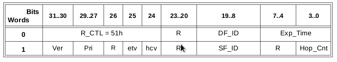
As you can see this header contains a source and destination Fabric ID in addition to some extra parameters which otherwise would get lost such as timeouts etc. The R_CTL value is now set at 0x51 indicating the IFR.
Encapsulation Header
Lastly int he extended header section there is the Encapsulation header. This is the simplest of them all and basically only is used when two IFR capable switches are used but there are no IFR capable switches in between these or they are transmitted through so called transit fabrics. Cisco’s IVR methodology uses this if transit VSAN’s are used. The only thing different in the frame header is then the R_CTL field which will be set to 0x52 therefore notifying that the content of the frame is a frame with proxied addresses.
Optional headers
The second section discusses “Optional Headers”. The optional headers are used INSIDE a normal FC frame and use the first 64 bytes of the payload of that frame. The usage of an optional header is depicted by bits 16&17, 21 and 22 in the DF_CTL field I mentioned before.
There are only 3 optional header defined
- ESP_Header & ESP_Trailer
- Network_header
- Device_header
The ESP (Encapsulating Security Payload) provides a method of encrypting the payload inside a FC frame. The usage is however defined in multiple separate standards from T11 and IETF. The ESP can be used in a link-by-link or even end-to-end.
The Network header is used in bridge or gateway environments between normal FC fabrics or between FC and non-fc networks. There are some use cases but its not often seen in the field.
The Device header is a field which is primarily used by an ULP protocol on the FC4 layer. This feature can be used if that specific protocol requires the addition of a header which it could otherwise transport via the FC network. IP-FC (or iFCP) is such a mechanism whereby IP packets are transported through the FC network.
This concludes the short overview of the FC frameheader extensions that are currently defined in the standards. Let me know if if you have additional questions or subjects and please complete the short survey at the top. Thanks
Regards,
Erwin van Londen

Dear Erwin, could you please clarify what happens when frames tagged by a Cisco Equipment on one side are received by a Brocade device on the other side. To be more precise, I am referring about the interconnection between UCS (FEX) and a Brocade device. By default, the FEX will tag traffic in VSAN 1. It means that somehow this tag should be included in the extension header. In this case, what happens when the brocade switch receives it. He simply does not take it into account and accept the traffic?
I was under the impression that VSAN were working the same way than VLAN. With VLAN,when a port is in access mode or untagged more, the frame is sent without 802.1q header at all. However, with VSAN, I did some tests that made me think that it behaves differently. When we connect a FEX in VSAN 1 to a MDS switch, there is communication only if the VSAN 1 is configured on the other side as well. It means that the VSAN ID is included in the header. However when we connect it to a Brocade switch that is not able to “speak” VSAN, there is still communication. Any idea how?
Thanks in advance.
Hello Gael,
I think the communication is limited to the ELP and EFP parameters. During initialization of the ISL the ELP (Exchange Link Parameters) checks whats on the other side. If its a switch it will pop into E-port mode and it resumes with EFP (Exchange Fabric Parameters) negotiation. It might well be that the ISL itself if fully operational but the fabrics will segment. I think a Cisco FEX sits in NPV mode by default and thus is unaware of any VSAN configuration.
Secondly don’t get mixed up with VLAN and VSAN. These are totally different and have nothing in common. Fibre-Channel N-ports do not “tag” frames per-se. There is only field they might use (CS_CTL) which is an obsolete byte in the frame header which was used in Class 1 and Class 4. I’ve personally never seen this byte being used. An N-port NEVER sets an extended or routing header.
Hope this helps.
Regards,
Erwin
Thanks Erwin. Cisco FEX sits in NPV mode by default, but most of the time, f-port-trunking feature is used as well. And in this case the traffic from the FEX goes into the switch with the VSAN tag. It is still not clear for me how a Brocade switch will process a frame with a VSAN tag from a Cisco equipment.
According to the white paper from Cisco (http://www.cisco.com/c/dam/en/us/products/collateral/servers-unified-computing/ucs-b-series-blade-servers/whitepaper_C07-730016.pdf), the tag is simply ignored by the
Brocade device, but there is no details about the way it works.
Regards,
Gael
Hi Gael,
There is no VSAN identifier between the FEX and the Brocade switch. The vHBA, VIC and FEX determine to which VSAN they belong but this is not propagated further. You can compare it a bit like portgroups in a Brocade terminology where the F-ports on the Access Gateway (NPIV switch) can be grouped to use one or more N-ports going to the rest of the fabric. These portgroups are also not propagated to the rest of the fabric. With the terminology differences across these two platforms it doesn’t make it easier but I hope I explained it a bit here.
Cheers
Erwin